|
ME 405
|


|
|
ME 405
|
|
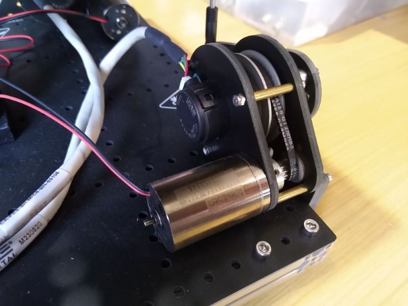
For the first week of our term project assignment, we checked and updated our encoder and motor drivers that we used last quarter in ME 305. The only initail functionality change was incorporating fault detection into the motor driver. The physical driver (DRV8847 motor driver) has a fault detection pin that is pulled low under a number of circumstances (thermal, over current, open load...). I added interrupt based fault handling to my motor driver. When a falling edge is detected on the 'nFAULT' an Interrupt Service Routine (ISR) is triggered that disables the motors in software and sets an internal driver fault attribute to True, latching the fault state. This latch prevents any further action that would supply power to the motors (enable() and set_duty()). Instead these methods route to a fault checking method that tests the value of the nFAULT. If the hardware fault has beeen cleared, the driver is unlatched and operations can continue.
Since we are using the two H-Bridges within the DRV8847 motor driver to control independent motors, they both share nSLEEP and nFAULT pins. Only one ISR can be attached to a pin, so I updated my motor driver constructor to allow the desegnation of a 'primary' motor. By setting this designator to True, the user can select which motor object will create the fault detection ISR and generate the interface prompts to clear the fault. When locked out due to a fault, the promary motor should be used to clear it. In practice, the nFAULT pin is reset through either some delay time due to hysteresis in the fault triggereing parameter (temp, current...) or through a power cycle. My driver implements code that cycles power upon user input until the fault has been cleared. Since both motor objects have control over the nSLEEP pin, both technically can be used to clear the fault, but only the primary motor will repond to the fault and provide feedback to the user.
To test this feature, I passed the user button to the driver as if it were the fault pin. I checked the fault detecting behavior by creating a loop that sets the duty of both motors once every second. I was able to trigger the fault ISR using the button. This disabled both motorsand prompted me to clear the fault.
I also spent time improving the test code included with both drivers. For both, I added simple terminal UIs which prompt the user to select different types of tests and which device to test. For both driver I made tests to time methods (timed tests) and output (running tests). In the motor driver, I also included a test that runs the motors through timed forward and backward movements and a test for fault detection. This testing code is tailored to the ME 405 hardware, and would need to be updated if used in a different setting.
When intergrating these two drivers into the final system, I ran into two issues that required changes to the motor driver. The first was a 'sticking' of the fault state in software. I found that when initialized the nFAULT pin momentarily triggers. When my driver tried to self correct, any attempt to unlatch the fault caused another edge on the nFAULT pin. To over come this, I disabled the fault ISR when my driver sucessfully latched the Fault state. I then added a 100 us delay after enabling my motors before turning on the ISR. This stopped the driver fault latch from sticking.
The other issue that I came across was the large dead band present in both of our motors. I found that for both axes, PWM duty percentages between around -30% - 30% resulted in little to no motion. This made it impossible to level my platform. When using reasonable gains, I was unable to consistently get closer than 5 degrees from level on both axes. I initially tried increasing my system gains, to raise the control signal outside of the motor's dead band at small angles. This overtuning worked, but made the system unstable when farther than 5 degrees off of level. I found an actual solution in a 2006 laberatory report produced by a Grand Valley State University enginereering student. In this report, this student provided a dead band compensation algorithim for bidirectional motor control.
After reading the report and reviewing the student's findings, I used the new test code that I added to my motor driver to sweep positive and negative PWM dutys for both motors. I found that my X and Y axis motors had dead band of (-28,28) and (-25,25). I added the motor dead band as an initialization argument for my motor object. This allowed me to adjust duty requests sent to the motor using the following equation:
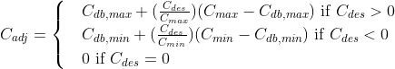
Here, C_adj is the adjusted output, C_des is the desired output, C_max and C_min are the pos and neg the maximum PWM values, and C_db,max and Cdb,min are the pos or neg dead band values. Using this alone resulted in high frequency vibrations as the motor bounced between positve and negative duty values. To fix this, I widened the range of desired PWM valuse for which the duty is set to 0. My final dead band compensation algorithm is shown below:
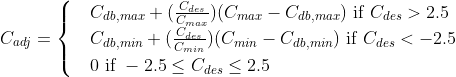
This motor driver change allowed me to sucessfully balance my platform reliably to within 1 degree of level. It also allowed me to reduce my controller gains by a factor of aproximately 50.
The paper that I referenced can be found at the following link:
Two python files was created for this assignemnt. The source code for this files can be found here: