|
ME 405
|


|
|
ME 405
|
|
The final two weeks of the quarter were spent intergrating all of the components of our term project into a functioning system. We used the model we developed and tested in Labs 0x06 and 0x07 to design a full state feedback controller for the system. To sense our system state and provide actuation, we interfaced with the motor, encoder, and touch pannel drivers that we had built previously. I also chose to interface with the BNO055 breakout board to provide an absolute orientation for my platform.
As the term project fit together, I came across a number of performance issues that required me to revisit the modeling calculations and hardware drivers. All of the term project pages and software documentation previously produced have been updated with a discussion of the changes that I implemented for the final integration. Please revist these sections to view the updates. This section will focus on how all of these changes came together and the final status of the project.
I began by revisiting the system model testing script that I wrote for Lab 0x07 and repurposed it as a controller design tool. Using the python control systems tool box, I used the Linear Quadratic Regulator (LQR) method to generate initail controller gains for both a reduced system containing only the platform and the full system. The script, system_ctrl_design.py, walks through my design process, and generates comparison plots to show the results of tuning. My partner Kyle Chuang completed a controller design hand analysis using pole placement and coefficent matching. His results confirmed the validity of both of our software based design techniques.
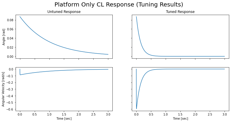
I followed the same tuning process for both the reduced and the full system. I started checking the system response to an initail 5 mm ball displacement with all my LQR weights set to 1. From there I began adjusting weights, starting with the R matrix (actualt effort weight). I reduced this to bring up the gains on my state variables. From there I increased the weights on the lower order terms and reduced the weights on the higher order terms. After the balancing software was functional, I used it to test analytically determined gain sets. The system response informed my weighting scheme. My analytical tuned an untuned gains for the platform system were:
Kplat_untuned = [-1.09643,  -0.996143]
  Kplat_tuned = [-10.0926,  -1.41904]
The following plot shows a comparison between the tuned and untuned reduced system model.
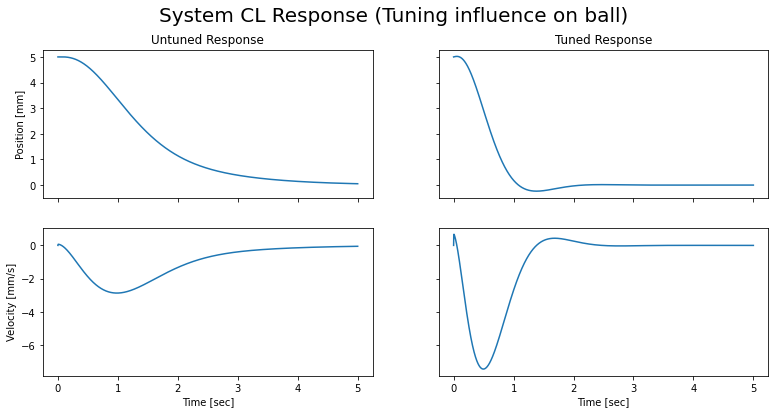
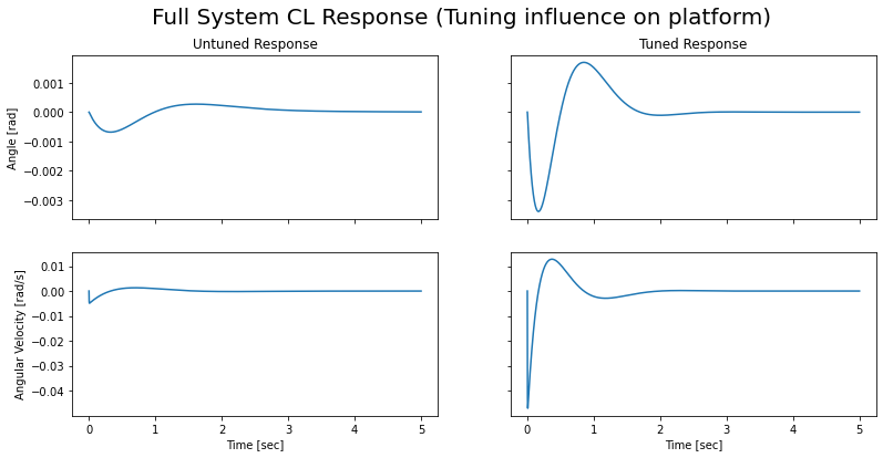
The tuning process for the full system was identical to that used on the reduced system. My analytical tuned an untuned gains for the whole system were:
Ksys_untuned = [-1.17333,   -4.90108,   -1.54464,   -1.02376]
  Ksys_tuned = [-10.1618,   -10.1002,   -5.43733,   -1.08662]
The following plots show a comparisons between the tuned and untuned reduced system model I broke the behavior of the platform and the ball into separate plots for clarity.
Once I had a controller gain set in which I felt confident, I started integrating all of the components of the term project into a main script. Before writing any code, I drew out how all of the peices fit together. The following image is the final version of my system diagram with important elements broken out:
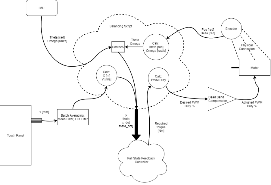
This diagram provided a very useful outline for creating my main balancing script. First I wrote a class for my full state feedback controller using the PID controller I created for ME 305 as a skeleton. Once this was working I brought in all of the relevant setup code for my other drivers and created a time controlled loop that read sensor data, passed the resulting the control signals to the motors. At a high level, my script operates in two modes. The first occurs when there is no contact detected on the touch pannel. In this state, the system is controlled using the gains derrived from the platform only model, and the orientation measurements from the BNO055 IMU. This allows for repeatable and automatic absolute leveling. When in this mode, the time that the platform is stable (no omega) is tracked. If there has been no motion for 50 controller cycles the encoders are zeroed.
The second mode begins when contact is detected on the touch pannel. The controller waits for 100 cycles with positive contact before changing the control system to incorperate the ball position and velosity. This was done to allow the ball position signal to stabalize before using it for control. The FIR filter and averaging scheme that I applied to reduce noise and accidental loss of contact also acts on the real contact changes. The easiest way to handle this was to add an artificial settling time before changing control state. In this mode, platform orientation data is read from the encoders. This allows for much faster controller speeds, and as a result, better performance.
Before attempting to balance the ball, I chose to focus on leveling the platform. I started with the tuned analytical controller that I had developed. for the reduced system. Initially,I was unsucessful due to the large deadband in the ME 405 kit motors. As I discussed in the motor driver section (Encoder & Motor Drivers) I solved this issue by adding dead band compensation to my motor driver. This change enabled my platform to level itself from any orientation to within 1 degree of level. I set 1 degree as the threshold because, outside of that, I could not reliably get the ball to stay on the platform. I found that my tuned gains for theta were far more adequate, with a slight increase, once the dead band compensator was active. The gain on omega, however, was far to high. In order to get a stable response, I had to reduce the gain on omega by a factor of ~100. I also increased slightly increade the the
My final manually tuned gains for the platform system were:
Kplaty = [-14.4129, -0.00223331]
Kplatx = [-10.4129, -0.00223331]
I tuned each axis sepatately to address the different levels of friction in the two drive assembies. The systems still has a tendancy to oscillate more than I would like, but reducing the gains led to a far less consistent final stable position. The following plots shows the system's response to a disturbance (me poking the -x,-y corner of the platofrm).
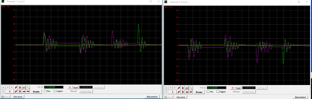
The left scope window shows the control signals, while the right shows platform angle as read by the BNO055 IMU. X data is shown in green, and y data is shown in purple. In this test I disturbed the plafor four times. The first time by pressing down on the (-x,-y) corner. The second time, by pressing up on the (-x,-y) corner. The final two disturbances were produced by pressing down on -x and -y axes individually.
Once the platform could reliably balance itself, I turned to incorperating the dynamics. At this point, I created the second operating mode discussed above. The first thing that I noticed was the poor quality of the signal coming from the touch pannel. The signal itself was noisy, but worse was the lask of consistent contact. I found that, especially near the edges of the platform, I would get contact loss that translated into percieved jumps in the ball's position. This lead to high frequency vibrations as the controll signal was pushed and pulld by the poor positional measurements. My toruble shooting process and eventualy solution is fully discussed in my signal filtering section (Fun with Filters). I was unable to fully clean up the touch pannel signal in the time I had available to finish this project. However, I was able to vastly imporve it. The lingering issues with the touch pannel data is a significant hurlde that is preventing form consistently balancing the ball on the platform.
As I was manually tuning the full system, I found that the gain on the ball's velocity was far too high (similar to the gain on omega). The poor position signaly quality on the was only amplified when I calculated velosity. This forced me to drom its gain by a factor of about 6 to achieve a stable response.
My final manually tuned gains for the whole system were:
Ksysy = [-14.17333, -14.4129,   -1.254464,  -0.00223331]
Ksysx = [-14.17333, -10.4129,   -1.254464,  -0.00223331]
The final performance of the balancing system was not what I hoped it would be, but it is far better than where I started. I still get high frequency jittering at the edges of the touch pannel that lead to a loss of stability. For very light disturbances of the ball, or of a larger object (a lime was used), I can stop the motion of the object, but I usually fail to bring it back to the center of the platform. This image shows the system response to balancing a lime on the platform. The performance depicted is not the highest possible since the controller cannot run at max speed while visualizing data, but it is adequate for demonstration purposes.
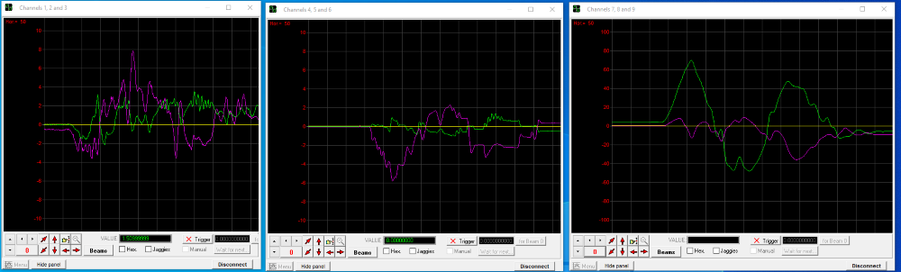
From left to right, the scope windows depict control signal, platform angle, and touch pannel position. The purple traces corespond to y axis values while the green traces corespond to x axis values. The y axis control signal (purlpe) responds to the y axis platform tilt (purple), and the x axis position (green). The x axis control signal (green) responds to the x axis platform tilt (green), and the y axis position (purple).
The following link leads to a video demonstration of my hardware with comenatry about the system:
Direct Video Link: https://youtu.be/ZhBD2UM5fwg
While I was unable to achive high performace with my system, the process of designing, troubleshooting, and tuning the system taught me a lot. This term project has been a great opportunity for me to deepen my understanding of mechatronics and to practice using my skills.
Three additional python files was created for the final part of this assignemnt. The source code for these files can be found here: